machine
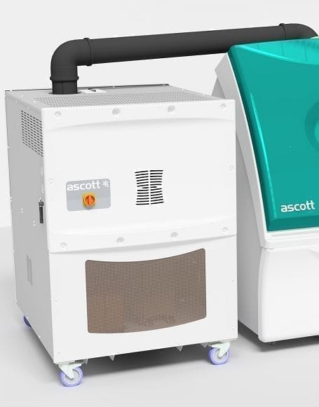
ATCU
ASCOTT ATCU -40 200 - 240VAC 3 PH
Details
- Status
- Active
- Description
- —
- Parent
- —
Images
Bill of materials
Total £0.00| Part | Description | Reference | Qty | Unit | Total | |
|---|---|---|---|---|---|---|
| No BOM lines. | ||||||
Wire numbers
87 wires| Wire | Name / definition | Optional extra | Notes | From | To | |
|---|---|---|---|---|---|---|
| 0 | AC neutral / control neutral | YES — SHAREDPsychometric Unit Option | Shared standard neutral. It also returns the GP35 pump circuit associated with the psychometric option. | |||
| 1 | 3-phase distribution conductor | NO | The '1' shown at the Psychometric Unit connector on page 3 is a connector pin, not this wire. | |||
| 10 | Stage 1 compressor phase conductor | NO | — | |||
| 100 | 3-phase power conductor | NO | — | |||
| 101 | 3-phase power conductor | NO | — | |||
| 102 | 3-phase power conductor | NO | — | |||
| 11 | Stage 2 compressor phase conductor | NO | — | |||
| 110 | Transformer secondary phase conductor | NO | — | |||
| 111 | Transformer secondary phase conductor | NO | — | |||
| 112 | Transformer secondary phase conductor | NO | — | |||
| 114 | Heater supply phase | NO | — | |||
| 115 | Heater supply phase | NO | — | |||
| 116 | Heater supply phase | NO | — | |||
| 12 | Stage 2 compressor phase conductor | NO | — | |||
| 122 | Condenser fan branch feed | NO | — | |||
| 123 | Condenser fan switched feed | NO | — | |||
| 124 | De-superheater fan branch feed | NO | — | |||
| 125 | De-superheater fan switched feed | NO | — | |||
| 126 | Crankcase-heater branch feed | NO | — | |||
| 127 | Crankcase heater stage 1 switched feed | NO | — | |||
| 128 | Crankcase heater stage 2 switched feed | NO | — | |||
| 13 | Stage 2 compressor phase conductor | NO | The '13' shown beside B1 on page 3 is a connector pin, not this power wire. | |||
| 14 | Heater phase feed after contactor C4 | NO | The '14' shown beside B1 on page 3 is a connector pin, not this power wire. | |||
| 15 | Heater phase feed after contactor C4 | NO | The '15' shown beside B1 on page 3 is a connector pin, not this power wire. | |||
| 150 | Stage 1 COOL solenoid feed | NO | — | |||
| 151 | Stage 1 BYPASS solenoid feed | NO | — | |||
| 152 | Stage 2 COOL solenoid feed | NO | — | |||
| 153 | Stage 2 BYPASS solenoid feed | NO | — | |||
| 154 | DEHUMID solenoid feed | NO | — | |||
| 16 | Heater phase feed after contactor C4 | NO | The '16' shown beside B2 on page 3 is a connector pin, not this power wire. | |||
| 164 | Plant healthy output | NO | — | |||
| 17 | Heater switched output | NO | — | |||
| 18 | Heater switched output | NO | — | |||
| 19 | Heater switched output | NO | — | |||
| 2 | 3-phase distribution conductor | NO | — | |||
| 210 | HEAT command | NO | — | |||
| 24 | +24 V DC control supply | NO | Page 1 standard: pink, 0.5 mm². The explicitly marked Psychometric Unit option does not show a direct 24 V wire connection. | |||
| 248 | GP35 pump switched AC feed | YESPsychometric Unit Option | Revision H states the psychometric fill/drain valves were replaced by a pump; this is the GP35 pump circuit. | |||
| 265 | RUN command | NO | — | |||
| 286 | HUMIDIFY command | NO | — | |||
| 289 | Psychometric option control signal | YESPsychometric Unit Option | Explicitly inside the area labelled 'PSYCHOMETRIC UNIT OPTION' and routed to SSR9. | |||
| 3 | 3-phase distribution conductor | NO | — | |||
| 4 | AC live / control supply feed | YES — SHAREDPsychometric Unit Option | Shared standard AC feed. SSR9 uses it to switch the optional GP35 psychometric pump. | |||
| 43 | Air circulation fan contactor command | NO | — | |||
| 44 | Stage 1 compressor contactor command | NO | — | |||
| 45 | Stage 2 compressor contactor command | NO | — | |||
| 46 | Heater contactor command before over-temperature interlock | NO | — | |||
| 5 | Air circulation fan phase conductor | NO | — | |||
| 50 | Stage 1 cooling-solenoid relay command | NO | — | |||
| 51 | Stage 1 bypass-solenoid relay command | NO | — | |||
| 52 | Stage 2 cooling-solenoid relay command | NO | — | |||
| 53 | Stage 2 bypass-solenoid relay command | NO | — | |||
| 54 | Dehumidification solenoid relay command | NO | Function follows the Q8-Q12 relay/solenoid sequence shown on page 3. | |||
| 55 | PLC output Q13 | NO | Function not defined by the source drawing. | |||
| 560 | DEHUMID command / control signal | NO | Dehumidifier is shown as part of the ATCU circuit and is not explicitly labelled optional. | |||
| 57 | Heater contactor command after OT2 | NO | — | |||
| 6 | Air circulation fan phase conductor | NO | — | |||
| 68 | COOL command | NO | — | |||
| 7 | Air circulation fan phase conductor | NO | The '7' shown at the Psychometric Unit connector on page 3 is a connector pin, not this wire. | |||
| 74 | Air temperature limit input | NO | — | |||
| 75 | PLC input I4 | NO | Function not defined by the source drawing. | |||
| 76 | PLC input I5 | NO | Function not defined by the source drawing. | |||
| 77 | PLC input I6 | NO | Function not defined by the source drawing. | |||
| 78 | PLC input I7 | NO | Function not defined by the source drawing. | |||
| 79 | Heater contactor feedback | NO | — | |||
| 8 | Stage 1 compressor phase conductor | 0 V DC common | YES — SHAREDPsychometric Unit Option | Context-specific use on the power circuit; the drawing also uses wire 8 as the 0 V DC identifier. Page 1 standard: violet, 0.5 mm². Shared 0 V rail; SSR9 for the psychometric option returns on wire 8. | |||
| 80 | Recirculation fan overload feedback | NO | — | |||
| 81 | Stage 1 compressor overload feedback | NO | — | |||
| 82 | Stage 2 compressor overload feedback | NO | — | |||
| 83 | Stage 1 pressure-switch feedback | NO | The drawing shows two Stage 1 HP/LP1 feedback conductors, 83 and 84. | |||
| 84 | Stage 1 pressure-switch feedback | NO | The drawing shows two Stage 1 HP/LP1 feedback conductors, 83 and 84. | |||
| 85 | Stage 2 pressure-switch feedback | NO | The drawing shows two Stage 2 HP/LP1 feedback conductors, 85 and 86. | |||
| 86 | Stage 2 pressure-switch feedback | NO | The drawing shows two Stage 2 HP/LP1 feedback conductors, 85 and 86. | |||
| 87 | Stage 2 HP1 feedback | NO | — | |||
| 9 | Stage 1 compressor phase conductor | NO | The '9' shown at the Psychometric Unit connector on page 3 is a connector pin, not this wire. | |||
| 92 | Heater SSR control | NO | — | |||
| 93 | Y3 solenoid command | NO | Drawing does not give a separate functional label for Y3. | |||
| E | Supply earth / protective earth | NO | Page 1 wire-identification standard. | |||
| L1 | Mains supply phase L1 | NO | Page 1 standard: black, 4 mm². | |||
| L11 | Phase conductor after main RCD | NO | — | |||
| L2 | Mains supply phase L2 | NO | Page 1 standard: black, 4 mm². | |||
| L21 | Phase conductor after main RCD | NO | — | |||
| L3 | Mains supply phase L3 | NO | Page 1 standard: black, 4 mm². | |||
| L31 | Phase conductor after main RCD | NO | — | |||
| R | Incoming supply phase identifier | NO | Supply label rather than a numbered control wire. | |||
| S | Incoming supply phase identifier | NO | Supply label rather than a numbered control wire. | |||
| T | Incoming supply phase identifier | NO | Supply label rather than a numbered control wire. |