machine
Salt Spray Premium
Ascott 120 - 1300
Details
- Status
- Active
- Description
- —
- Parent
- —
Images
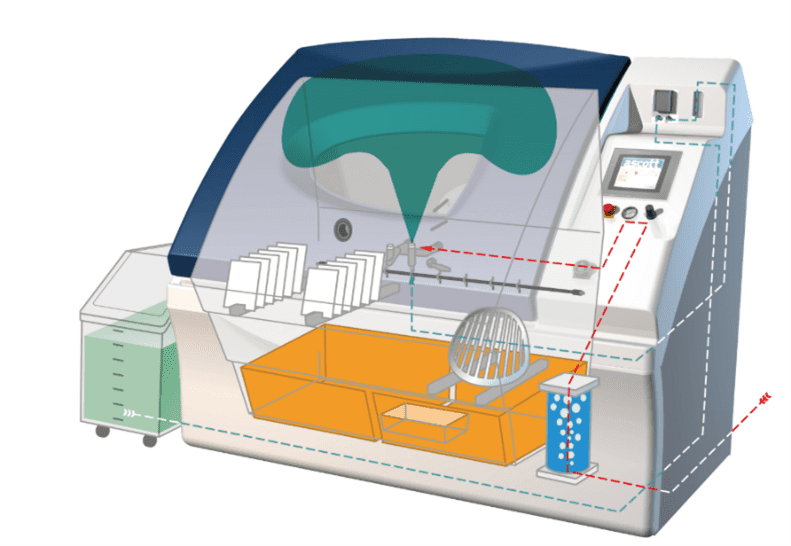
Bill of materials
Total £0.00| Part | Description | Reference | Qty | Unit | Total | |
|---|---|---|---|---|---|---|
| No BOM lines. | ||||||
Wire numbers
65 wires| Wire | Name / definition | Optional extra | Notes | From | To | |
|---|---|---|---|---|---|---|
| 1 | Cabinet mains live distribution feed from the mains filter / RCBO path to K30 L1 and page 3 circuits | NO | Listed on page 1 as a cabinet-mains (>3 A) wire identifier. | |||
| 10 | O/T 1 over-temperature input | NO | Page 4 shows wire 10 from the O/T chain to the PLC. | |||
| 1004 | Air-saturator heater branch between K1 and MCB4 | NO | — | |||
| 101 | Switched mains live bus from K30 feeding heater relay contacts | NO | Feeds K10 and K2 directly and K1 through MCB4. | |||
| 107 | Cabinet heater E4/B model-specific load conductor | NO | Shown for models B, C, D, F, G, J, K and L. | |||
| 108 | Cabinet heater E4/C model-specific load conductor | NO | Shown for models B, C, D, J, K and L. | |||
| 11 | O/T 2 input and over-temperature safety link to K30 | NO | Wire 11 also connects the O/T chain to relay K30 A1 on page 3. | |||
| 123 | ACC20 full-switch input | YESACC20 — option | — | |||
| 125 | ACC92 scrubber-flow input | YESACC92 — Scrubber Flow Meter | — | |||
| 132 | Pump M2 red motor lead between F2V2 and PERC010 | NO | — | |||
| 14 | Moist air solenoid Y4 command | NO | — | |||
| 144 | Internal-illumination protected live feed from MCB3 to K17 contacts | YESInternal Illumination (OPTION) | — | |||
| 147 | Salt-tank low-water alarm input | NO — MODEL DEPENDENT | Page 7 states NOT FITTED TO A AND I MODELS; it is not explicitly labelled as an option in this issue. | |||
| 15 | Switched mains live conductor between Q1 and the RCBO | NO | Used in both mains-filter arrangements. | |||
| 16 | Protected neutral interconnect from the RCBO to ELEC516.1 | NO | Shown in the non-integral mains-filter arrangement. | |||
| 163 | High-water input | NO — MODEL DEPENDENT | Page 4 shows the high-water optical sensor circuit fitted to models A and I only. | |||
| 173 | Water LOW input | NO | — | |||
| 18 | Emergency-stop status input | NO | — | |||
| 19 | Canopy opened switch input | NO | Page 4 shows the pneumatic sensor-switch circuit. | |||
| 190 | Cabinet mains (>3 A) identifier listed in the wire standard | NO | Not otherwise observed on pages 2-7 of this issue. | |||
| 2 | Cabinet mains neutral / common return to heater and accessory circuits | YES — SHAREDInternal Illumination option — shared mains return | Also returns the optional internal-illumination lamp circuit. | |||
| 20 | Air-saturator auto-fill solenoid Y1 command | NO | — | |||
| 200 | Cabinet mains (>3 A) identifier listed in the wire standard | NO | Not otherwise observed on pages 2-7 of this issue. | |||
| 2000 | Immersion-heater neutral-side conductor shown at E7/A | NO | Page 1 revision F references neutral wire 2000; later revision G says neutral is no longer through the contactor. Page 3 still labels E7/A with 2000. | |||
| 21 | Air-saturator FULL optical sensor input | NO | — | |||
| 22 | Air-saturator LOW optical sensor input | NO | — | |||
| 236 | Canopy-open solenoid conductor after the emergency-stop contacts | NO | Connects S4 to the canopy OPEN solenoid Y10. | |||
| 237 | Canopy-close solenoid conductor after the emergency-stop contacts | NO | Connects S4 to the canopy CLOSE solenoid Y11. | |||
| 24 | +24 V DC control rail | YES — SHAREDHUMA030 RH1; ACC20; ACC92; ACC102; ACC05 and optional I/O — shared +24 V rail | — | |||
| 25 | Open-canopy command on PLC / emergency-stop side | NO | Passes through S4; the solenoid-side conductor is wire 236. | |||
| 26 | Dry air solenoid Y3 command | NO | — | |||
| 27 | Close-canopy command on PLC / emergency-stop side | NO | Passes through S4; the solenoid-side conductor is wire 237. | |||
| 28 | Canopy closed proximity-switch input | NO | — | |||
| 31 | Pump M1 black motor lead between F2V1 and PERC010 | NO | — | |||
| 32 | Pump M2 black motor lead between F2V2 and PERC010 | NO | — | |||
| 34 | Buzzer command | NO | — | |||
| 35 | Air-saturator heater E2 load conductor to relay K1 | NO | Listed on page 1 as a cabinet-mains (>3 A) wire identifier. | |||
| 36 | Air-saturator heater relay K1 control | NO | — | |||
| 37 | Chamber / cabinet heater relay K2 control | NO | PLC page labels this output CHAMBER HEATER. | |||
| 38 | Immersion-heater relay K10 control | NO | — | |||
| 39 | Cabinet heater E4/A load conductor to relay K2 | NO | Other model-specific cabinet-heater branches use wires 107 and 108. | |||
| 4 | Protected AC live distribution from MCB2 to the 24 V PSU and accessory branch | YES — SHAREDInternal Illumination option — shared protected live feed | Feeds PLCC303 L and the optional internal-illumination MCB3 branch. | |||
| 44 | Internal-illumination switched lamp / relay-contact conductor | YESInternal Illumination (OPTION) | Shown only inside the INTERNAL ILLUMINATION (OPTION) box. | |||
| 45 | Internal-illumination relay K17 command | YESInternal Illumination (OPTION) | — | |||
| 470 | Guardian Angel fatal-error warning | YESACC05 — Guardian Angel (OPTION) | — | |||
| 471 | Guardian Angel non-fatal error warning | YESACC05 — Guardian Angel (OPTION) | — | |||
| 472 | Guardian Angel system-healthy output | YESACC05 — Guardian Angel (OPTION) | — | |||
| 5 | Pump M1 red motor lead between F2V1 and PERC010 | NO | — | |||
| 54 | Immersion heater E7/A load conductor to relay K10 | NO | Listed on page 1 as a cabinet-mains (>3 A) wire identifier; used on models B, C, J and K. | |||
| 58 | Air-curtain solenoid Y33 command | NO | — | |||
| 59 | Base-fill solenoid group command | NO | Page 3 shows wire 59 driving the base-fill valve group. | |||
| 6 | HUMA030 RH1 humidity-probe analogue signal (white lead) | YESHUMA030 RH1 humidity probe (OPTIONAL) | HUMA030 RH1 is explicitly shown inside an OPTIONAL box. | |||
| 60 | Optional-accessory output; page 6 says AIR SATURATOR MANUAL FILL, page 7 shows HIGH WATER LEVEL lamp | YES — OPTIONAL I/OOptional accessories card / High Water Level circuit | The drawing gives two different function labels for wire 60; both are retained here rather than reconciled. | |||
| 63 | O/T 8 over-temperature input | NO | — | |||
| 64 | O/T 7 over-temperature input | NO | — | |||
| 65 | O/T 12 over-temperature input | NO | PLC page labels wire 65 O/T 12; page 4 shows it as a branch from the additional O/T chain. | |||
| 7 | Purge solenoid Y5 command | NO | — | |||
| 76 | Pump 1 pulse / speed command | NO | — | |||
| 77 | Pump 2 pulse / speed command | NO | — | |||
| 8 | 0 V DC control rail | YES — SHAREDHUMA030 RH1; ACC20; ACC92; ACC102; ACC46; ACC05; Internal Illumination — shared 0 V rail | — | |||
| 83 | SO2 fill solenoid Y26 command | YESACC46 — SO2 Fill | — | |||
| 87 | Mains live interconnect in the filter / RCBO path | NO | Its position changes with the integral vs non-integral filter arrangement. | |||
| 88 | Filtered neutral interconnect from ELEC514 toward Q1 | NO | Shown in the mains-filter-integral-to-connector arrangement. | |||
| 9 | PNEC069 S5 air-pressure sensor analogue signal (black lead) | NO | Brown/blue are supply/return; wire 9 is the signal into PLCC017. | |||
| 96 | Air-saturator heater-inhibit optical sensor input | NO | — |