machine
CYCLIC
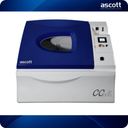
ASCOTT CC2600IP
Details
- Status
- Active
- Description
- —
- Parent
- —
Images
Bill of materials
Total £0.00Wire numbers
240 wires| Wire | Name / definition | Optional extra | Notes | From | To | |
|---|---|---|---|---|---|---|
| 1 | Incoming main-supply cable/core marking on L1 | NO | Shown beside the L1 conductor; may be a cable core number rather than the global wire-number scheme. | |||
| 10 | O/T 1 over-temperature input | NO | — | |||
| 100 | Filtered mains phase feed from Z1; also feeds accessory branches | YES — SHAREDMultiple option/accessory branches — shared mains feed/return | — | |||
| 1000 | Switched heater mains phase from contactor K30 | NO | — | |||
| 1001 | Switched heater mains phase from contactor K30 | NO | — | |||
| 1002 | Switched heater mains phase from contactor K30 | NO | — | |||
| 1004 | Air-saturator heater protected live branch after MCB8 | NO | — | |||
| 101 | Filtered mains phase feed from Z1; feeds 24 V PSU / ACC30 branch | YES — SHAREDACC30 — Salt Spray Vertically Down; shared mains feed | — | |||
| 102 | Filtered mains phase feed from Z1; used by heater/option branches | YES — SHAREDLiquid Immersion Reservoir / Interface / other option branches — shared mains feed | — | |||
| 11 | O/T 2 over-temperature input | NO | — | |||
| 113 | O/T 6 to blower E5/B interconnect (2000L/2600L) | NO | — | |||
| 1133 | User programmable digital output 2 command | YESUser Programmable Digital Output option | — | |||
| 115 | Pump 2 F2V2 / K6 drive interconnect | NO | — | |||
| 116 | Pump 2 F2V2 / K6 drive interconnect | NO | — | |||
| 117 | ACC46 SO2 fill solenoid Y26 switched feed from relay K102 | YESACC46 — Sulphur Dioxide Dosing | — | |||
| 1180 | User programmable digital output 2 relay K21 / X14 interconnect | YESUser Programmable Digital Output option | — | |||
| 1181 | User programmable digital output 2 relay K21 / X14 interconnect | YESUser Programmable Digital Output option | — | |||
| 1182 | User programmable digital output 2 relay K21 / X14 interconnect | YESUser Programmable Digital Output option | — | |||
| 1183 | User programmable digital output 2 relay K21 / X14 interconnect | YESUser Programmable Digital Output option | — | |||
| 123 | ACC20 full switch input | YESACC20 — Waste Water Trough & Pump System | — | |||
| 1233 | User programmable digital output 4 command | YESACC34 — Liquid Immersion Reservoir / Interface; User Programmable Digital Output option | — | |||
| 125 | ACC92 scrubber flow input | YESACC92 — Exhaust Salt Scrubber | — | |||
| 1265 | ACC29 butterfly valve | YESACC29 — Refrigeration & Humidity Control / ATCU | — | |||
| 132 | Pump M2 red motor lead | NO | — | |||
| 133 | User programmable digital output 1 command | YESUser Programmable Digital Output option | — | |||
| 134 | Spot cooler relay K27 coil +24 V feed | YESACC90 — Spot Cooler | Revision M states K27 A1 is permanently 24 V. | |||
| 139 | ACC47 rapid-transition extra heater-mat feed | YESACC47 — Rapid Transition / Blower Ball Valve | — | |||
| 14 | Moist air solenoid Y4 | NO | — | |||
| 140 | Salt solution consumption sensor ACC102 signal (black lead) | YESACC102 — Salt Solution Consumption Sensor | — | |||
| 144 | Interior illumination protected live feed through MCB12/K17 | YESACC26 — Interior Illumination | — | |||
| 147 | Salt tank low water alarm | YESACC59 — Salt Tank Low Water Alarm option family | — | |||
| 148 | BV3 blower ball-valve position-switch interconnect (2000L+) | YESACC39 — Blower Ball Valve; ACC47 — Rapid Transition / Blower Ball Valve | — | |||
| 1580 | User programmable digital output 4 relay K33 / X14 interconnect | YESUser Programmable Digital Output option | — | |||
| 1581 | User programmable digital output 4 relay K33 / X14 interconnect | YESUser Programmable Digital Output option | — | |||
| 1582 | User programmable digital output 4 relay K33 / X14 interconnect | YESUser Programmable Digital Output option | — | |||
| 1583 | User programmable digital output 4 relay K33 / X14 interconnect | YESUser Programmable Digital Output option | — | |||
| 159 | Liquid-immersion header-tank / N-trap valve control bus | YESACC34 — Liquid Immersion Reservoir / Interface | — | |||
| 164 | ATCU OK status | YESACC29 — Refrigeration & Humidity Control / ATCU | — | |||
| 170 | Blower ball-valve position input | YESACC39 — Blower Ball Valve; ACC47 — Rapid Transition / Blower Ball Valve | — | |||
| 173 | Water LOW input | NO | — | |||
| 174 | Liquid-immersion LOW indicator/control line via X6 | YESACC34 — Liquid Immersion Reservoir / Interface | — | |||
| 177 | ACC29 pump changeover/selection relay coil enable | YESACC29 — Refrigeration & Humidity Control / ATCU | — | |||
| 18 | Emergency stop input | NO | — | |||
| 180 | User programmable digital output 1 relay K20 / X14 interconnect | YESUser Programmable Digital Output option | — | |||
| 181 | User programmable digital output 1 relay K20 / X14 interconnect | YESUser Programmable Digital Output option | — | |||
| 182 | User programmable digital output 1 relay K20 / X14 interconnect | YESUser Programmable Digital Output option | — | |||
| 183 | User programmable digital output 1 relay K20 / X14 interconnect | YESUser Programmable Digital Output option | — | |||
| 189 | Phase conductor after MCB26, before EMI/filter Z1 | NO | — | |||
| 1891 | Phase conductor after 25 A RCD, before MCB26 | NO | — | |||
| 19 | Canopy opened input | NO | — | |||
| 191 | Spot cooler power branch after MCB15 | YESACC90 — Spot Cooler | — | |||
| 197 | Liquid-immersion fill/control bus; also K14 command path | YESACC34 — Liquid Immersion Reservoir / Interface | — | |||
| 198 | Heater over-temperature count signal | NO | — | |||
| 2 | Incoming main-supply cable/core marking on L2 | AC neutral/common return used throughout heater and option circuits | NO | YES — SHAREDMultiple option/accessory branches — shared mains feed/return | This conflicts with other page-2+ uses of '2' as neutral/common, so treat as local/core marking. | Also appears as an incoming cable/core label on page 2; do not assume global uniqueness without page context. | |||
| 20 | Auto fill solenoid Y1 | NO | — | |||
| 204 | Empty-base pump motor M8 lead | YESACC34 — Liquid Immersion Reservoir / Interface | — | |||
| 205 | Empty-base pump motor M8 lead | YESACC34 — Liquid Immersion Reservoir / Interface | — | |||
| 206 | Fill-base pump motor M7 lead via relay K14 | YESACC34 — Liquid Immersion Reservoir / Interface | — | |||
| 207 | Fill-base pump motor M7 lead via relay K14 | YESACC34 — Liquid Immersion Reservoir / Interface | — | |||
| 21 | Air saturator FULL optical sensor | NO | — | |||
| 210 | Heat command | YESACC29 — Refrigeration & Humidity Control / ATCU | — | |||
| 211 | Chamber full liquid-immersion switch SW21 signal | YESACC34 — Liquid Immersion Reservoir / Interface | — | |||
| 212 | Chamber liquid-immersion O/T13 signal | YESACC34 — Liquid Immersion Reservoir / Interface | — | |||
| 213 | Remote PAUSE input | YESRemote START/STOP/PAUSE/UNPAUSE accessory interface | — | |||
| 214 | Remote UNPAUSE input | YESRemote START/STOP/PAUSE/UNPAUSE accessory interface | — | |||
| 215 | Remote START input | YESRemote START/STOP/PAUSE/UNPAUSE accessory interface | — | |||
| 216 | Remote STOP input | YESRemote START/STOP/PAUSE/UNPAUSE accessory interface | — | |||
| 217 | Two-button canopy option input | YESTwo-button canopy option | — | |||
| 22 | Air saturator LOW optical sensor | NO | — | |||
| 220 | Chart recorder B5 brown lead | YESChart recorder option | — | |||
| 221 | Chart recorder B5 white lead | YESChart recorder option | — | |||
| 233 | User programmable digital output 3 command | YESACC34 — Liquid Immersion Reservoir / Interface; User Programmable Digital Output option | — | |||
| 236 | Canopy open solenoid circuit | NO | — | |||
| 237 | Canopy close solenoid circuit | NO | — | |||
| 24 | +24 V DC control rail | YES — SHAREDMultiple optional accessories — shared DC control rail | — | |||
| 241 | ACC46 SICK safety-relay input/internal safety circuit line | YESACC46 — Sulphur Dioxide Dosing | — | |||
| 242 | ACC46 SICK safety-relay output/reset internal line | YESACC46 — Sulphur Dioxide Dosing | — | |||
| 244 | ACC46 safety reset circuit line | YESACC46 — Sulphur Dioxide Dosing | — | |||
| 248 | ACC46 purge timer / canopy-open-safe PLC input signal | YESACC46 — Sulphur Dioxide Dosing | Page 7 calls it ACC46 PURGE TIMER; page 26 labels the same wire as PLC I2 CANOPY OPEN. | |||
| 249 | SO2 dose feedback | YESACC46 — Sulphur Dioxide Dosing | — | |||
| 25 | Open canopy command | NO | — | |||
| 250 | K16 T1 to immersion heater E6/A | Air bar / ACC46 purge air bar output | YES | YES — SHAREDACC34 — Liquid Immersion Reservoir / Interface | ACC46 — Sulphur Dioxide Dosing; standard Air Bar output | Same wire number is also used for Air Bar on pages 4/7/26; page context is essential. | |||
| 252 | Salt spray motor run | YESACC30 — Salt Spray Vertically Down | — | |||
| 253 | K16 T2 to immersion heater E6/B | YESACC34 — Liquid Immersion Reservoir / Interface | — | |||
| 254 | K16 T3 to immersion heater E6/C | YESACC34 — Liquid Immersion Reservoir / Interface | — | |||
| 255 | K15 to K16/A L1 interconnect | YESACC34 — Liquid Immersion Reservoir / Interface | — | |||
| 256 | K15 to K16/B L2 interconnect | YESACC34 — Liquid Immersion Reservoir / Interface | — | |||
| 257 | K15 to K16/C L3 interconnect | YESACC34 — Liquid Immersion Reservoir / Interface | — | |||
| 258 | K15 coil A1 control line | YESACC34 — Liquid Immersion Reservoir / Interface | — | |||
| 259 | K15 coil A2 control line | YESACC34 — Liquid Immersion Reservoir / Interface | — | |||
| 26 | Dry air solenoid Y3 | NO | — | |||
| 260 | O/T15 / base-fill thermostat chain | YESACC34 — Liquid Immersion Reservoir / Interface | — | |||
| 261 | O/T16 / base-fill thermostat chain | YESACC34 — Liquid Immersion Reservoir / Interface | — | |||
| 262 | O/T12 / base-fill thermostat chain | YESACC34 — Liquid Immersion Reservoir / Interface | — | |||
| 265 | Run command | YESACC29 — Refrigeration & Humidity Control / ATCU; ACC112 — MIDI Dehumidification Unit; ACC125 — ACTU interface option | — | |||
| 27 | Close canopy command | NO | — | |||
| 270 | TEMC036 terminal 1 control loop | YESACC34 — Liquid Immersion Reservoir / Interface | — | |||
| 271 | K16 coil A1 / TEMC036 terminal 16 control line | YESACC34 — Liquid Immersion Reservoir / Interface | — | |||
| 272 | K16 coil A2 / TEMC036 terminal 3 control line | YESACC34 — Liquid Immersion Reservoir / Interface | — | |||
| 275 | Liquid-immersion L1 after MCB12, into contactor K15 | YESACC34 — Liquid Immersion Reservoir / Interface | — | |||
| 276 | Liquid-immersion L2 after MCB13, into contactor K15 | YESACC34 — Liquid Immersion Reservoir / Interface | — | |||
| 277 | Liquid-immersion L3 after MCB14 / controller supply bus | YESACC34 — Liquid Immersion Reservoir / Interface | — | |||
| 28 | Canopy closed input / ACC46 canopy-closed safety signal | YES — SHAREDACC46 — Sulphur Dioxide Dosing | — | |||
| 282 | Liquid-immersion 3-phase L1 after isolator Q2, before MCB12 | YESACC34 — Liquid Immersion Reservoir / Interface | — | |||
| 283 | Liquid-immersion 3-phase L2 after isolator Q2, before MCB13 | YESACC34 — Liquid Immersion Reservoir / Interface | — | |||
| 284 | Liquid-immersion 3-phase L3 after isolator Q2, before MCB14 | YESACC34 — Liquid Immersion Reservoir / Interface | — | |||
| 286 | Humidify command | YESACC29 — Refrigeration & Humidity Control / ATCU | — | |||
| 289 | P_Fill command | YESACC29 — Refrigeration & Humidity Control / ATCU | — | |||
| 3 | Incoming main-supply cable/core marking on L3 | NO | Shown beside the L3 conductor; may be a cable core number rather than the global wire-number scheme. | |||
| 31 | Pump M1 black motor lead | NO | — | |||
| 311 | Air curtain | YESACC96 — Air Curtain pneumatic option | — | |||
| 32 | Pump M2 black motor lead | NO | — | |||
| 320 | Cabinet PT100, white lead | NO | — | |||
| 321 | Cabinet PT100, red lead | NO | — | |||
| 322 | Cabinet PT100, red lead | NO | — | |||
| 323 | Air saturator PT100, white lead | NO | — | |||
| 324 | Air saturator PT100, red lead | NO | — | |||
| 325 | Air saturator PT100, red lead | NO | — | |||
| 326 | Psychrometric wet PT100, white lead | NO | — | |||
| 327 | Psychrometric wet PT100, orange lead | NO | — | |||
| 328 | Psychrometric wet PT100, red lead | NO | — | |||
| 329 | Psychrometric dry PT100, yellow lead | NO | — | |||
| 33 | Blower ball valve(s) with position switch(es) | YESACC39 — Blower Ball Valve; ACC47 — Rapid Transition / Blower Ball Valve | — | |||
| 330 | Psychrometric dry PT100, green lead | NO | — | |||
| 331 | Psychrometric dry PT100, brown lead | NO | — | |||
| 332 | ACC34 option PT100, white lead | YESACC34 — Liquid Immersion Reservoir / Interface | — | |||
| 333 | ACC34 option PT100, red lead | YESACC34 — Liquid Immersion Reservoir / Interface | — | |||
| 334 | ACC34 option PT100, red lead | YESACC34 — Liquid Immersion Reservoir / Interface | — | |||
| 34 | Buzzer | NO | — | |||
| 35 | Air saturator heater E2 load-side conductor to relay K1 | NO | — | |||
| 352 | ACC30 vertically-down salt-spray motor M9 switched motor lead | YESACC30 — Salt Spray Vertically Down | — | |||
| 353 | ACC30 relay K19 switched supply bus | YESACC30 — Salt Spray Vertically Down | — | |||
| 36 | Air saturator heater control | NO | — | |||
| 37 | Chamber heater control | NO | — | |||
| 374 | ACC20 run-switch return / waste-water trough interface | YESACC20 — Waste Water Trough & Pump System | — | |||
| 375 | ACC20 waste-water trough motor/relay interconnect | YESACC20 — Waste Water Trough & Pump System | — | |||
| 377 | Sulphur dioxide supply valve | YESACC46 — Sulphur Dioxide Dosing | — | |||
| 38 | Immersion heater control | NO | — | |||
| 39 | Chamber heater mat load-side conductor | NO | — | |||
| 4 | Incoming main-supply cable/core marking on N | 24 V power-supply AC live feed after MCB6; also accessory live feed | NO | YES — SHAREDMultiple option/accessory branches — shared mains feed/return | This conflicts with later use of '4' as an AC live accessory/PSU feed, so treat as local/core marking. | The drawing also shows 1-4 as incoming cable core labels; context matters. | |||
| 401 | 8-channel analogue output card channel 3 / additional-pump speed-control bus | YESACC25 — ECC1 Additional Atomisers; ACC32 — Water Fog; ACC86 — Multi Solution Spray | — | |||
| 402 | Multi-solution spray motor M16 command | YESACC86 — Multi Solution Spray | — | |||
| 403 | 8-channel analogue output card channel 1 / additional-pump speed-control bus | YESACC25 — ECC1 Additional Atomisers; ACC32 — Water Fog; ACC86 — Multi Solution Spray | — | |||
| 404 | Multi-solution spray motor M17 command | YESACC86 — Multi Solution Spray | — | |||
| 405 | Additional atomiser motor M10 command | YESACC25 — ECC1 Additional Atomisers | — | |||
| 406 | 8-channel analogue output card channel 4 / additional-pump speed-control bus | YESACC25 — ECC1 Additional Atomisers; ACC32 — Water Fog; ACC86 — Multi Solution Spray | — | |||
| 407 | 8-channel analogue output card channel 2 / additional-pump speed-control bus | YESACC25 — ECC1 Additional Atomisers; ACC32 — Water Fog; ACC86 — Multi Solution Spray | — | |||
| 410 | ACC25 additional atomiser M10 / F2V3 / relay K23 interconnect | YESACC25 — ECC1 Additional Atomisers | — | |||
| 412 | ACC25 additional atomiser M10 / F2V3 / relay K23 interconnect | YESACC25 — ECC1 Additional Atomisers | — | |||
| 413 | ACC86 multi-solution M16/M17 / F2V9-F2V10 / relay K28 interconnect | YESACC86 — Multi Solution Spray | — | |||
| 414 | ACC86 multi-solution M16/M17 / F2V9-F2V10 / relay K28 interconnect | YESACC86 — Multi Solution Spray | — | |||
| 415 | ACC25 additional atomiser M11 / F2V4 interconnect | YESACC25 — ECC1 Additional Atomisers | — | |||
| 416 | ACC86 multi-solution M17 / F2V10 interconnect | YESACC86 — Multi Solution Spray | — | |||
| 417 | ACC25 additional atomiser M11 / F2V4 interconnect | YESACC25 — ECC1 Additional Atomisers | — | |||
| 418 | ACC86 multi-solution M17 / F2V10 interconnect | YESACC86 — Multi Solution Spray | — | |||
| 419 | ACC32 water-fog M12/M13 / F2V5-F2V6 / relay K24 interconnect | YESACC32 — Water Fog | — | |||
| 422 | ACC32 water-fog M12/M13 / F2V5-F2V6 / relay K24 interconnect | YESACC32 — Water Fog | — | |||
| 424 | ACC32 water-fog M13 / F2V6 interconnect | YESACC32 — Water Fog | — | |||
| 425 | ACC32 water-fog M13 / F2V6 interconnect | YESACC32 — Water Fog | — | |||
| 426 | ACC86 multi-solution M14/M15 / F2V7-F2V8 / relay K26 interconnect | YESACC86 — Multi Solution Spray | — | |||
| 427 | ACC86 multi-solution M14/M15 / F2V7-F2V8 / relay K26 interconnect | YESACC86 — Multi Solution Spray | — | |||
| 428 | ACC86 multi-solution M15 / F2V8 interconnect | YESACC86 — Multi Solution Spray | — | |||
| 429 | ACC86 multi-solution M15 / F2V8 interconnect | YESACC86 — Multi Solution Spray | — | |||
| 430 | Compressor command (Comp) | YESACC29 — Refrigeration & Humidity Control / ATCU | — | |||
| 431 | ACC25 additional atomiser M10 / F2V3 / relay K23 interconnect | YESACC25 — ECC1 Additional Atomisers | — | |||
| 432 | ACC25 additional atomiser M10 / F2V3 / relay K23 interconnect | YESACC25 — ECC1 Additional Atomisers | — | |||
| 433 | ACC25 additional atomiser M10 / F2V3 / relay K23 interconnect | YESACC25 — ECC1 Additional Atomisers | — | |||
| 434 | ACC25 additional atomiser M10 / F2V3 / relay K23 interconnect | YESACC25 — ECC1 Additional Atomisers | — | |||
| 435 | ACC32 water-fog M12/M13 / F2V5-F2V6 / relay K24 interconnect | YESACC32 — Water Fog | — | |||
| 436 | ACC32 water-fog M12/M13 / F2V5-F2V6 / relay K24 interconnect | YESACC32 — Water Fog | — | |||
| 437 | ACC32 water-fog M12/M13 / F2V5-F2V6 / relay K24 interconnect | YESACC32 — Water Fog | — | |||
| 438 | ACC32 water-fog M12/M13 / F2V5-F2V6 / relay K24 interconnect | YESACC32 — Water Fog | — | |||
| 439 | ACC86 multi-solution M14/M15 / F2V7-F2V8 / relay K26 interconnect | YESACC86 — Multi Solution Spray | — | |||
| 44 | Interior illumination lamp P10 switched lead | YESACC26 — Interior Illumination | — | |||
| 440 | ACC86 multi-solution M14/M15 / F2V7-F2V8 / relay K26 interconnect | YESACC86 — Multi Solution Spray | — | |||
| 441 | Salt scrubber valve | YESACC92 — Exhaust Salt Scrubber | — | |||
| 442 | ACC86 multi-solution M14/M15 / F2V7-F2V8 / relay K26 interconnect | YESACC86 — Multi Solution Spray | — | |||
| 443 | ACC86 multi-solution M14/M15 / F2V7-F2V8 / relay K26 interconnect | YESACC86 — Multi Solution Spray | — | |||
| 444 | ACC86 multi-solution M16/M17 / F2V9-F2V10 / relay K28 interconnect | YESACC86 — Multi Solution Spray | — | |||
| 445 | ACC86 multi-solution M16/M17 / F2V9-F2V10 / relay K28 interconnect | YESACC86 — Multi Solution Spray | — | |||
| 446 | ACC86 multi-solution M16/M17 / F2V9-F2V10 / relay K28 interconnect | YESACC86 — Multi Solution Spray | — | |||
| 447 | ACC86 multi-solution M16/M17 / F2V9-F2V10 / relay K28 interconnect | YESACC86 — Multi Solution Spray | — | |||
| 45 | Interior illumination relay command | YESACC26 — Interior Illumination | — | |||
| 450 | Purge valve for salt spray | YESACC30 — Salt Spray Vertically Down | — | |||
| 463 | Pressure release valve for salt spray | YESACC30 — Salt Spray Vertically Down | — | |||
| 470 | Guardian Angel - fatal error warning | YESACC05 — Guardian Angel | — | |||
| 471 | Guardian Angel - non-fatal error warning | YESACC05 — Guardian Angel | — | |||
| 472 | Guardian Angel - system healthy | YESACC05 — Guardian Angel | — | |||
| 474 | Additional atomiser motor M11 command | YESACC25 — ECC1 Additional Atomisers | — | |||
| 475 | 8-channel analogue output card channel 0 / additional-pump speed-control bus | YESACC25 — ECC1 Additional Atomisers; ACC32 — Water Fog; ACC86 — Multi Solution Spray | — | |||
| 48 | Blower heater control | YES — OPTIONAL I/OPLCC015-1 optional digital-output card (blower heater connection) | — | |||
| 480 | Spraybar parked sensor | YESACC31 — Oscillating Spray Bar | — | |||
| 5 | Pump M1 red motor lead | NO | — | |||
| 50 | Wash down valve | YESACC42 — Wall Wash Down | — | |||
| 500 | Oscillating spray bar motor engage | YESACC31 — Oscillating Spray Bar | — | |||
| 502 | Oscillating spray-bar motor M19 drive lead | YESACC31 — Oscillating Spray Bar | — | |||
| 54 | Immersion heater E7 load-side conductor to relay K10 | NO | — | |||
| 560 | De-humidify command | YESACC29 — Refrigeration & Humidity Control / ATCU; ACC112 — MIDI Dehumidification Unit; ACC125 — ACTU interface option | — | |||
| 563 | 8-channel analogue output card channel 6 / additional-pump speed-control bus | YESACC25 — ECC1 Additional Atomisers; ACC32 — Water Fog; ACC86 — Multi Solution Spray | — | |||
| 564 | 8-channel analogue output card channel 5 / additional-pump speed-control bus | YESACC25 — ECC1 Additional Atomisers; ACC32 — Water Fog; ACC86 — Multi Solution Spray | — | |||
| 58 | Salt spray air valve | YESAdditional pump facility — optional salt-spray air solenoid | — | |||
| 580 | User programmable digital output 3 relay K32 / X14 interconnect | YESUser Programmable Digital Output option | — | |||
| 581 | User programmable digital output 3 relay K32 / X14 interconnect | YESUser Programmable Digital Output option | — | |||
| 582 | User programmable digital output 3 relay K32 / X14 interconnect | YESUser Programmable Digital Output option | — | |||
| 583 | User programmable digital output 3 relay K32 / X14 interconnect | YESUser Programmable Digital Output option | — | |||
| 59 | Base fill | NO | — | |||
| 6 | RH1 humidity sensor signal, white lead | NO | — | |||
| 60 | High water warning lamp | YESACC66 — High Water Warning Lamp | — | |||
| 63 | O/T 8 over-temperature input | NO | — | |||
| 64 | O/T 7 over-temperature input | NO | — | |||
| 65 | O/T 12 over-temperature input | NO | — | |||
| 68 | Cool command | YESACC29 — Refrigeration & Humidity Control / ATCU | — | |||
| 71 | Liquid-immersion interface status/control line via X6 | YESACC34 — Liquid Immersion Reservoir / Interface | — | |||
| 72 | Liquid-immersion HIGH indicator/control line via X6 | YESACC34 — Liquid Immersion Reservoir / Interface | — | |||
| 73 | Liquid-immersion OK indicator/control line via X6 | YESACC34 — Liquid Immersion Reservoir / Interface | — | |||
| 74 | Pump 1 F2V1 / K6 drive interconnect | NO | — | |||
| 75 | Pump 1 F2V1 / K6 drive interconnect | NO | — | |||
| 76 | Pump 1 pulse | NO | — | |||
| 77 | Pump 2 pulse; reused by ACC46 as PLC Q1 SO2 demand/timer input | YESACC46 — Sulphur Dioxide Dosing | Function depends on option configuration. | |||
| 8 | 0 V DC control rail | YES — SHAREDMultiple optional accessories — shared DC control rail | — | |||
| 85 | Base drain (close) | NO | — | |||
| 87 | Phase conductor after MCB26, before EMI/filter Z1 | NO | — | |||
| 871 | Phase conductor after 25 A RCD, before MCB26 | NO | — | |||
| 88 | Phase conductor after MCB26, before EMI/filter Z1 | NO | — | |||
| 881 | Phase conductor after 25 A RCD, before MCB26 | NO | — | |||
| 9 | Air pressure sensor S5 signal, black lead | NO | — | |||
| 900 | Air pressure 1 switch input | NO | — | |||
| 91 | Low air input | NO | — | |||
| 92 | Liquid-immersion base-empty valve / relay control bus | YESACC34 — Liquid Immersion Reservoir / Interface | — | |||
| 93 | Liquid-immersion heater/control relay K13 command | YESACC34 — Liquid Immersion Reservoir / Interface | — | |||
| 96 | Air saturator heater inhibit | NO | — | |||
| 97 | Blower heater load-side conductor to relay K3 | NO | — | |||
| 98 | O/T 3 to blower E5/A interconnect | NO | — | |||
| E | Supply earth | NO | — | |||
| L1 | Mains supply phase L1 | NO | — | |||
| L2 | Mains supply phase L2 | NO | — | |||
| L3 | Mains supply phase L3 | NO | — | |||
| N | Mains neutral | NO | — | |||
| N2 | Neutral conductor after 25 A RCD / through filter path | NO | — | |||
| PE symbol | Cabinet earth | NO | — |